|
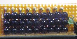
The system was designed to produce an intense flash of 880nm infrared light
using an array of 27 LEDs. The LEDs were driven hard but for only 100ms at a time.
I had my doubts that even after 1000s of flashes the LEDs would not be producing the same
amount of light.
After I had received the documentation package, I discovered that extensive
changes had been made by someone else long after I was no longer involved with the
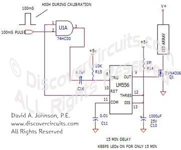
project. To my shock, I saw a 555 timer circuit being used as a 15 minute timer.
I questioned my old client. Yes, they had made changes. One of
the last additions I was asked to make to the original circuit was to provide a means to
control the LEDs through a computer link. The link was to be used only during
initial calibration so the LEDs could be aligned properly so they all pointed at the
center of a large projection screen. But, it seemed that under certain conditions the LEDs
could indeed be left turned on all night. This only occurred when the power to the
LED box was left on while the computer system it was connected to was turned off.
This cooked the LEDs. The 15 minute timer was added to prevent the LEDs from being turned
on for more than 15 minutes at a time. I knew immediately what the problem was.
A 555 timer is a great device and has been used for thousands of short
timing applications. But, it is not good for timing situations when the time
stretches out to many minutes. As in many simple timers, the 555 timer relies on a
simple resistor and capacitor time constant to generate the time delay. As an
example, a 1M resistor and a 10uF capacitor will work as a 10 second timer. A 10M
resistor and a good 10uF capacitor will produce a 100 second time. I myself have
used similar circuits with the 555 timer for simple timing functions out to 3 minutes or
so. Beyond 3 minutes or so there is a very real possibility that the timer will not
time out. The reason? Leakage! As the capacitor values grow larger to produce
a longer and longer RC time constant, the capacitor leakage current can often exceed the
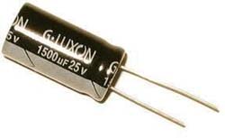
charging current through the resistor. As shown in the drawing below, my client’s
circuit used a 1M resistor and a 1000uF capacitor to form a 15 minute timer. This
might have worked when the capacitor was new and if the capacitor was at room temperature.
But, as the device aged and if it were used inside a warm enclosure, the leakage could
dramatically increase. As soon as the leakage current exceeded the charging current,
the capacitor would never charge up to the 2/3 supply voltage needed to reset the 555
timer. As the capacitor aged, the times would gradually increase until they became
infinite.
|
|
|
15 Minute Timer
Circuit |
If you were look at almost any aluminum electrolytic capacitor data sheet
you will find a leakage figure such as “I = 0.01CV”, were C is the capacitance and V is
the applied voltage. I is the leakage current in Amps. A 1000uF cap charged up
to 5v could, by the data sheet, have a leakage current of 50 microamps. Holy Cats!
When used with a 1M resistor and a 5v supply the maximum charging current would be only 5
microamps. So, an older capacitor would never charge up and the 555 timer circuit
would wait forever. No wonder the poor LEDs were cooking. There really isn’t a
simple way to correct this circuit. Even the best of electrolytic capacitors will
still have unacceptable leakage currents. I you were to increase the resistor value to
say 22M with a 47uF electrolytic cap, the lower leakage would still be offset by a much
lower charging current. The best solution would be to replace the 555 timer circuit with
a digital timer, which uses an oscillator and a multi-stage counter to form at long time
delay. The cost would be minimal and since no large capacitor would be needed, the
circuit would not take up much more board space. The lesson here is that a 555 timer
should never be used for times beyond about 3 minutes or so. |